The 50MHz Assistant
(Preamp & Power Amp.) 
By Alkberto, I0XGR
Issue 31 & 31 October 1991 & January 1992
Alberto is a First class technician and keen constructor, he developed the Assistant for use at 1A0KM and HV3SJ. The Assistant is the name given by Alberto to his 50MHz linear and preamplifier design.
 |
| The Cicuit Diagram of the Assistant Pre-amplifier. |
The preamplifier is the most important part of the whole unit, due to it being a narrowband amplifier it is mandatory in order to avoid receiver front-end overload especially that caused by nearby TV carriers and other unwanted garbage near our band.
The heart of the pre-amplifier is a dual-gate mosfet type BF981 or similar. This device is capable of givig 25dB gain with a low noise figure, maybe not quite as important at 50MHz than at 144MHz or above, but a good feature all the same.
The tuned input circuit allows good selectivity with a small loss, because of the Q-load/Q-unoladed ratio. The low loss is achieved by the use of good quality variable capacitors and silvered wire for the coils. The output band-pass filter cuts out all the unwanted signals stil present and giving excellent selectivity. By using the selectable output attenuator, you can choose the correct amount of gain for your receiver. Keep in mind however that increasing the gain too much may result in receiver overload.
 |
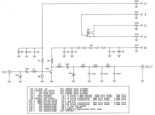
| Circuit Diagram of Power Amplifier |
At 0dB gain the preamplifier can be regarded as a band-pass filter without insertion loss. It was decided not to include diode protection at theinput of the pre-amplifier, this is to avoid generating the problems we have worked to eliminate! When a strong signal is present, diodes rectify it, thus generating white noise and a lot of harmonic signals and there is no way we want that! To tune the pre-amplifier a noise generator and a sweep generator should be used if you have one.
In issue 31 of Six News Alberto explained how to build the pre-amp section of this project. In part two of his article we will look at the linear amplifier, PTT Controller, and main board..
 |
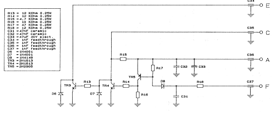
| The PTT Controller |
The linear power amplifier is capable of 100 watts output with 12 watts drive, which means a power gain of about 9.5 dB The employed transistor is a Motorola MRF-422 running at 30V and capable of up to 150 watts output at 30MHz. However I advise not to exceed this limit in order to avoid splatter. The linearity is quite good and a test made with the two tone method, showed a third order inter-modulation distortion of -35 dB at 100 watts PEP output. If your transmitter is a splatter generator, please treat it before building a power amplifier! The idle current must be set at 150mA by adjusting the value of R4, which is located outside the amplifier box to avoid overheating. The diode D5 must be screwed near TR1 (on an adequate heat sink) to assure good thermal feedback. The reason for a bolt diode is not its dissipation capability, but for best thermal coupling with the heat sink. Running at full power the amplifier all the harmonic signals are well below -70dBc.
The power supply is very simple and a number of tests have shown that making use of good quality components, the voltage stabilization for the power amplifier is unnecessary. In particular the value of the filter capacitor should be as high as possible. The main line socket has a built-in fuse and a radio frequency filter.
 |
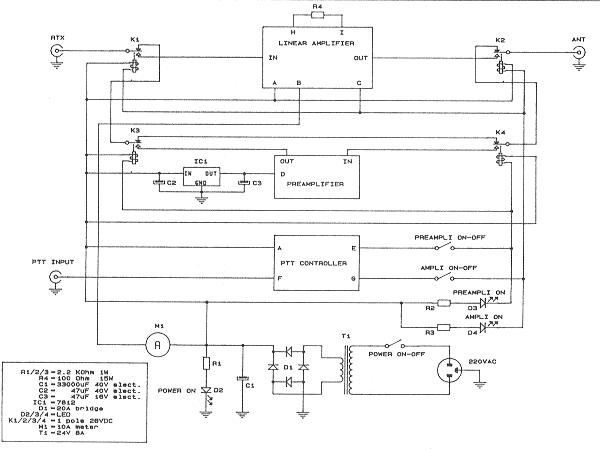
| The Main Board |
To switch both the amplifier and pre-amplifier, the use of four coaxial relays seems to be the lest solution but the overall cost rises very quickly In the prototype I used four single pole 28V relays, shielded one from the other with copper-clad sheet. The RF wiring is made with adequate size 50 Ohm Teflon coaxial cable.
Three metallic tinned boxes house the main units of the Assistant (pa controller, amplifier and pre amplifier) A standard single sided, copper-clad board is cut to size and tinned. Teflon press-fit terminals. inserted at key locations are used to support component leads. Ground connections are made by soldering directly to the tinned board.
Wishing you good DX with the aid of the 50MHz ASSISTANT. I'll be QRV for any questions or criticisms.
Alberto, I0XGR
![]() To return to the Archives page
click here
To return to the Archives page
click here